|
|
Chapter 2� : Build of a 143% Steve Bage MIG17 Inlet/Outlet ducting, fan installation and electronics. Introduction :
Chapter 1 of the build showed assembly of the balsa components. This article shows
how the inlet and outlet ducts were fabricated and installation of the power
units and controller. Inlet and outlet ducts :
Steve�s original used paper� ducts
which I was not keen on. A colleagues EDF model flown in damp weather �bubbled�
its ducts due to water absorption. At the inlet, the high air velocity leads
to a decrease in static pressure (Bernouilli) and
as water vapour dissolves out it is absorbed by the paper leading to damage
and distortion of the paper ducts. I searched the workshop for suitable formers, 45mm for the
inlet and 36mm for the outlet and found nothing. Eventually I used acrylic
tube from clear plastic supplies. My first attempt was to sneak some baking parchment from
the Domestic Controller and wrap the formers with this using Magic tape. I
then wrapped wetted Gummed Brown Paper of the type used by picture framers,
around the former. After 24hrs drying the duct was removed. Alas the duct
failed in buckling as I struggled to push fit it into the fuselage. Now if
the former had been 0.5mm smaller or if I had sanded the formers, I might
have stood a chance. As it was, I abandoned Gummed Brown Paper and used
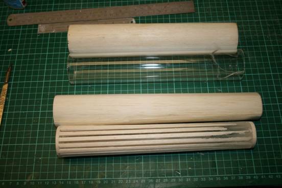
conventional techniques of well sanded 1/32� 6lb/ft^3 balsa with tissue/doped
x 3 interior for damp proofing. These came out at 5.1gm and 6gm outlet/inlet which is not
unacceptable bearing in mind that a sheet of A4 printer paper is 5gm. The
ducts are shown below next to their formers. Note that the outlet (lower)
duct is tapered. The 36mm�
acrylic former is shown with tapered balsa packers to achieve a
44/36mm taper.
The observant will notice that the inlet former is cracked
on the right edge. The EDF blew it off the bench on test despite there being
a 5� separation, but it glued together OK. Moral :
Do not work messy�easily said but not easy�
to achieve. EDF tests : These were
repeated with the intent battery, a 550 mah 25C
Hyperion G3 from Robotbirds. Allegedly capable of
13.7amps. Current draw was initially 13.2 amps, dropping to 12.3 amps steady
after 10s. This data is similar to the tests run in Chapter 1. I admit that I
turned the kpaero controller down to just over 10
amps as the thrust I judged to be more than adequate�..time will tell. I am
very impressed with this EDF unit. Buy here and dead cheap but I cannot fault this transaction. Performance claims�a tad extravagant but not that far off. EDF installation: ���I installed the outlet duct using CA
tacking with dilute�
PVA grouting applied with a paint brush. The EDF went in with
CA tacks and UHU Por fillets (a touch of compliance
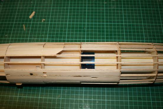
to absorb stray motor vibration). The inlet duct was installed as the outlet
duct. I added a tissue/dope reinforcement to the
underside of the inlet duct at the battery/controller section. The structure
appears to be super stiff. I cannot imagine that the fuselage structure will
fail. The stringering was completed as shown below.
If the EDF needs attention, major� surgery will be necessary as the
power unit is not serviceable. I still have the option of separation at F7
but will need a motor failure before I get the panel saw out. With hindsight, I would probably instal
the balsa formers much earlier and before stringering
as some sanding of the former inside diameters was necessary for a snug
sliding fit.
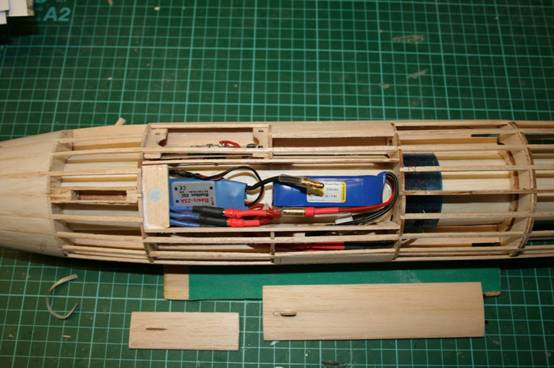
I felt it prudent to use 3.5mm connectors as I could� not rule out
having to use a 3 cell battery. Now these were bulky so the battery and ESC
load as below in the intent space . Hatch retention
is via magnet.
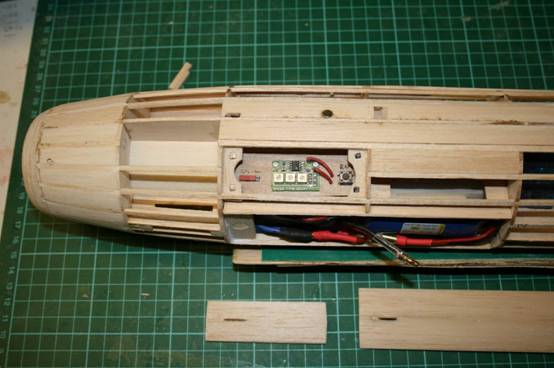
The kpaero E30 flight controller
loads to a bay created underwing, again with� magnet hatch
retention. The left hand slide switch connects battery to controller and the
right hand push switch starts the timed motor run. Both switches are sub
micro as they only have to cope with the current load of the� kpaero
controller believed to be less than 10ma. On model retrieval, I have to switch off the controller on
the slider, leaving the 3.5mm battery plugs connected. After the last flight
of the day, move the slider to the off position and disconnect one or both
3.5mm battery plugs and remove the battery for storage.
Note that I have added 1/16� balsa infill just under the
wing in the region where the model is gripped for launch. A quick run up before lunch confirmed that I had connected
the ESC motor correctly and had not messed up the switch soldering. I need to do a few hours more sanding and filling, then
covering and finish. Ian Middlemiss Jan 2012� [email protected] |