|
Making a Peterborough Timer for the Ferry 500
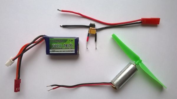
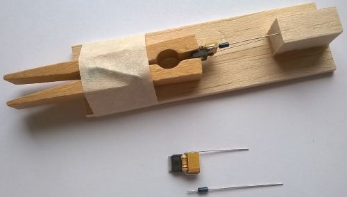
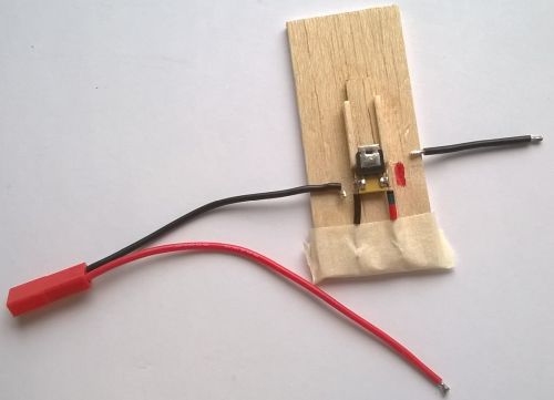
The Ferry 500 E20 model uses a Peterborough FET Timer with a fixed 8 second run. This is the simplest version of the timer with a single resistor. To start the motor the timer terminals are ‘zapped’ with fully charged 9V battery. Adding a diode prevents damage from accidentally reversing polarity when zapping. For convenience, the timer is assembled on a JST pigtail which is the standard connector for the 2S 180mAh Lipo flight battery. This connector can be changed to 2mm gold bullets to save some space.
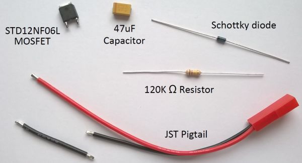
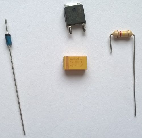
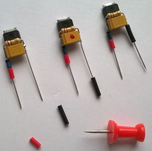
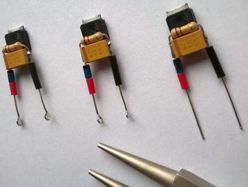
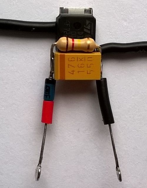
Components
The assembled timer weighs 1 gram without wires. It is possible to use smaller components and reduce the weight (SOT-223 FET package and B-Case Capacitor, 0.125W resistor) but this version is robust and the components are a practical size for soldering. The above components give around 8-9 seconds run on the GWS CN12 brushed motor. Using different sized components or motors can vary the time, so some experimenting with different resistances might be required.
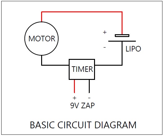
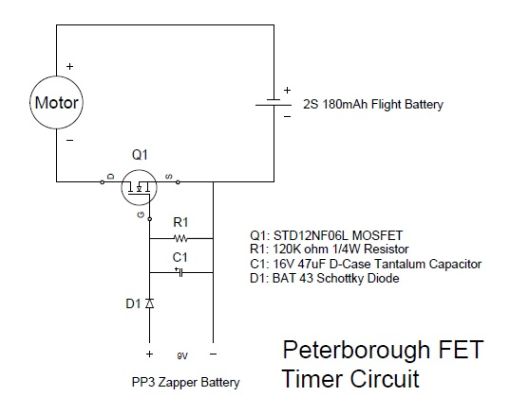
Circuit Details The timer is inserted into the lipo/motor circuit on the negative wire as shown on this schematic.
A full circuit diagram is shown below.
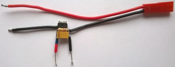
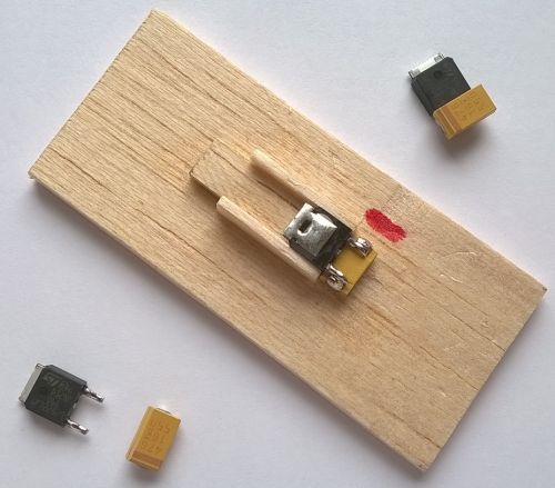
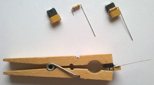
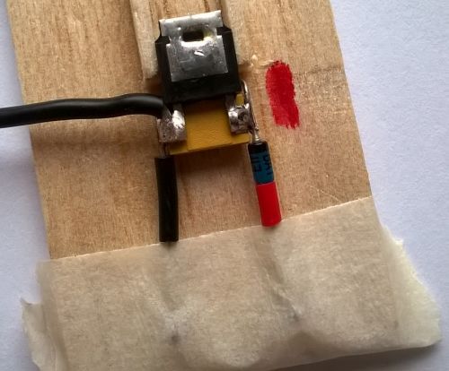
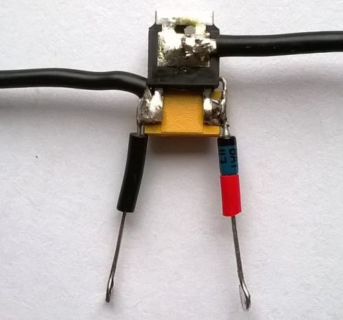
Video Tutorial The following videos provide a full tutorial on making a Ferry 500 timer: The following photos show some of the details covered in the videos:
Jonathan Whitmore
Click for an easy to print .pdf download of the above information.
|
||||||||||||||||||||